Marten Electric 電気テン @ Home
Vintage audio gear connoisseur, computer enthusiast, time nut, music lover, vintage games gamer, nerd, tinkerer and shady electronic projects makerEurocard DIN41612 3U Prototyping board PCB card 220 x 100mm
Introduction
I have originally designed this PCB for few of my project, but this turn out so well that I have now posted all schematic, gerber files and documentation to fellow enthusiast such as yourself. Perhaps (and I hope) content in this obscured corner of interwebs will inspire you to start your own projects.
Eurocard is a European standard format for printed circuit board (PCB) cards that can be plugged together into a ![]() standard chassis sub-rack which, in turn, can be mounted in a 19-inch rack. The chassis consists of a series of slotted card guides on the top and bottom, into which the cards are slid so they stand on end, like books on a shelf. At the spine of each card is one or more connectors which plug into mating connectors on a backplane that closes the rear of the chassis.
standard chassis sub-rack which, in turn, can be mounted in a 19-inch rack. The chassis consists of a series of slotted card guides on the top and bottom, into which the cards are slid so they stand on end, like books on a shelf. At the spine of each card is one or more connectors which plug into mating connectors on a backplane that closes the rear of the chassis.
Eurocards system in generally is enormously versatile for all kinds of projects thanks to standardized mechanical dimensions and quality connectors. Eurocards PCB's come in many sizes (wikipedia article). This is single height most common size 3U single height x 160mm card. I have also designed 3U Prototyping board PCB card 160 x 100mm if you require bigger prototype card. You can use these card in industry standard DIN subrack or Eurorack. Card will fit nicely in PCB guide rails with front panel Eurorack if you wish to use one.
Card has been designed to be very versatile and you can fit DIN connectors each side if you wish or DIN connector / Eurorack front panel configuration.
Card can also be stacked with others (use standard 2.5mm / 3.00m diameter PCB spacer and simply just prototype your project on them.
These boards look absolutely gorgeous in standard green solder mask if you going for that standard industrial look.
I can advise you where to buy connector and front panel holder.
(≧︿≦)
Except where otherwise noted, content on this site is licensed under a Creative Commons Attribution 4.0 International license. CC-BY-4.0
I have created content on this website free to use for personal, educational and commercial purposes. If you like or use my work, please mention me or perhaps consider a donation.
| or |
... but if you feel like getting something for nothing isn't your cup of tea (completely understandable) (ಥ﹏ಥ) and a prefer to support me and get something back in return, then you can purchase directly on my eBay or Tindie shop. However if you are still up for an adventure */in very positive way/* (and are happy to have PCB's made yourself in your favourite PCB house - PCBWay is highly recommended), then carry on, download gerber files and have fun! ( ͡° ͜ʖ ͡°)


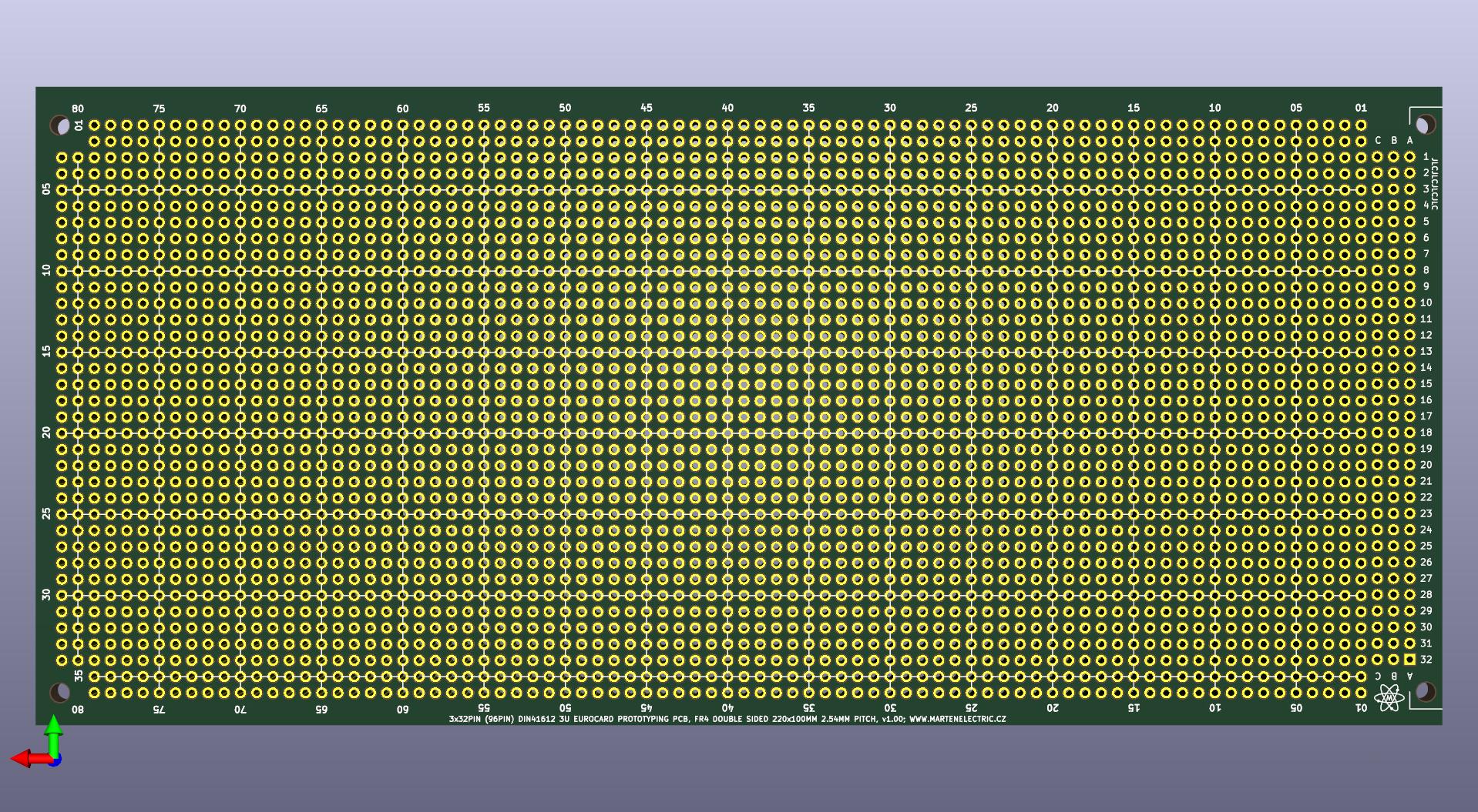
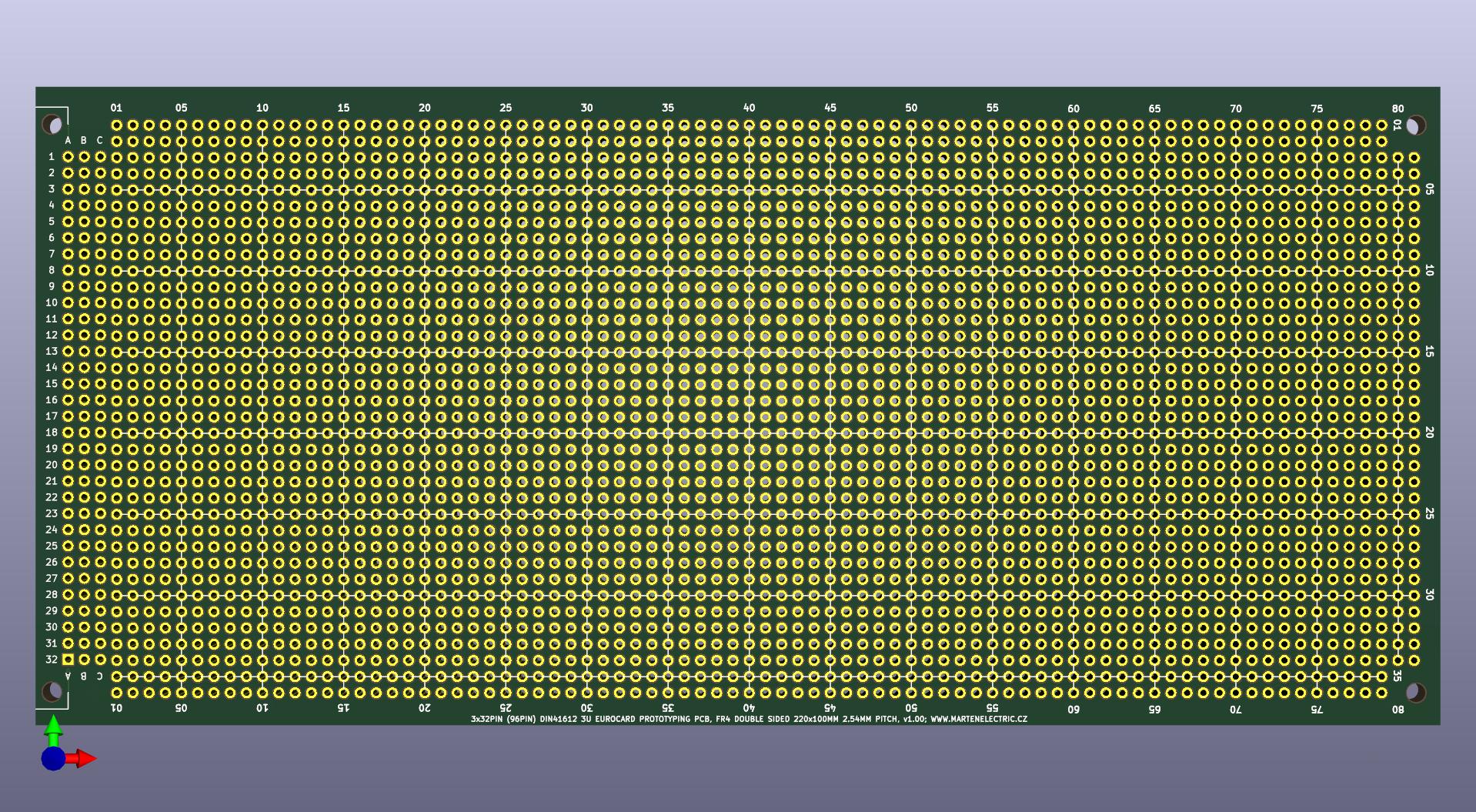
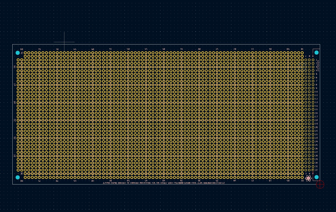
EDA preview
click on pictures to enlarge
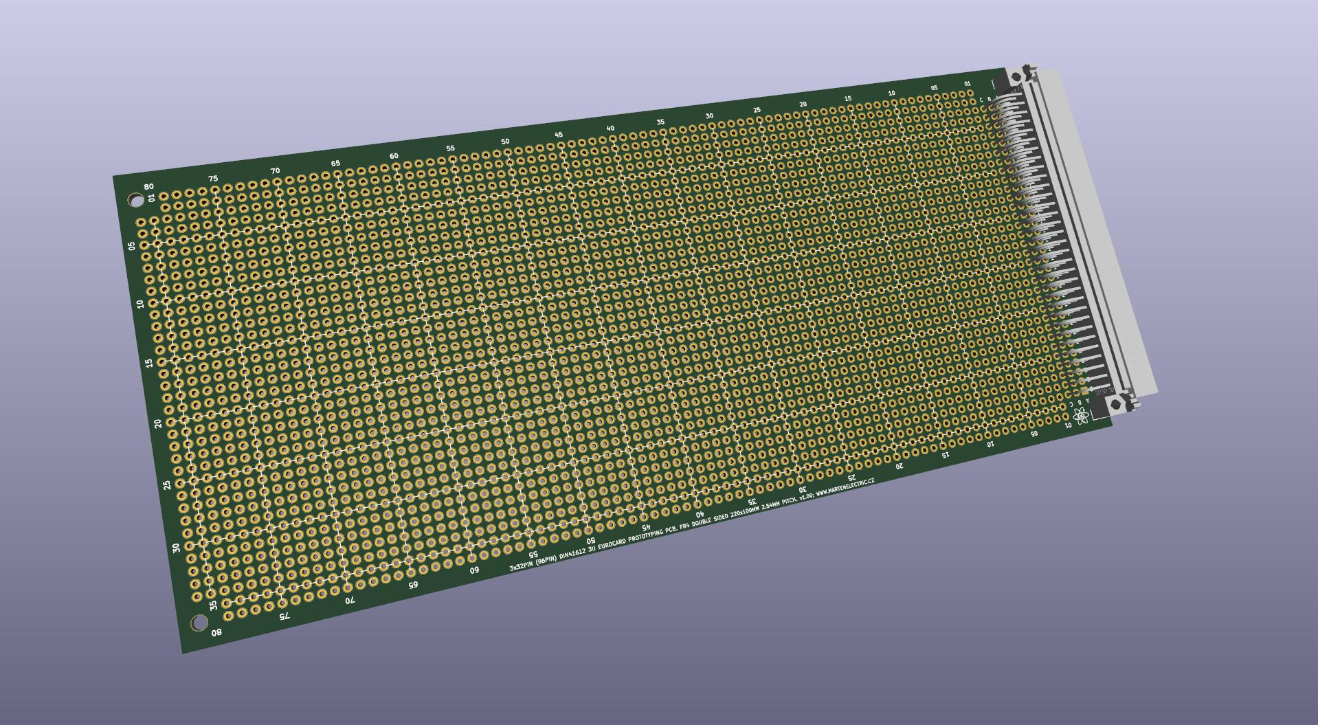
3d render v1.0
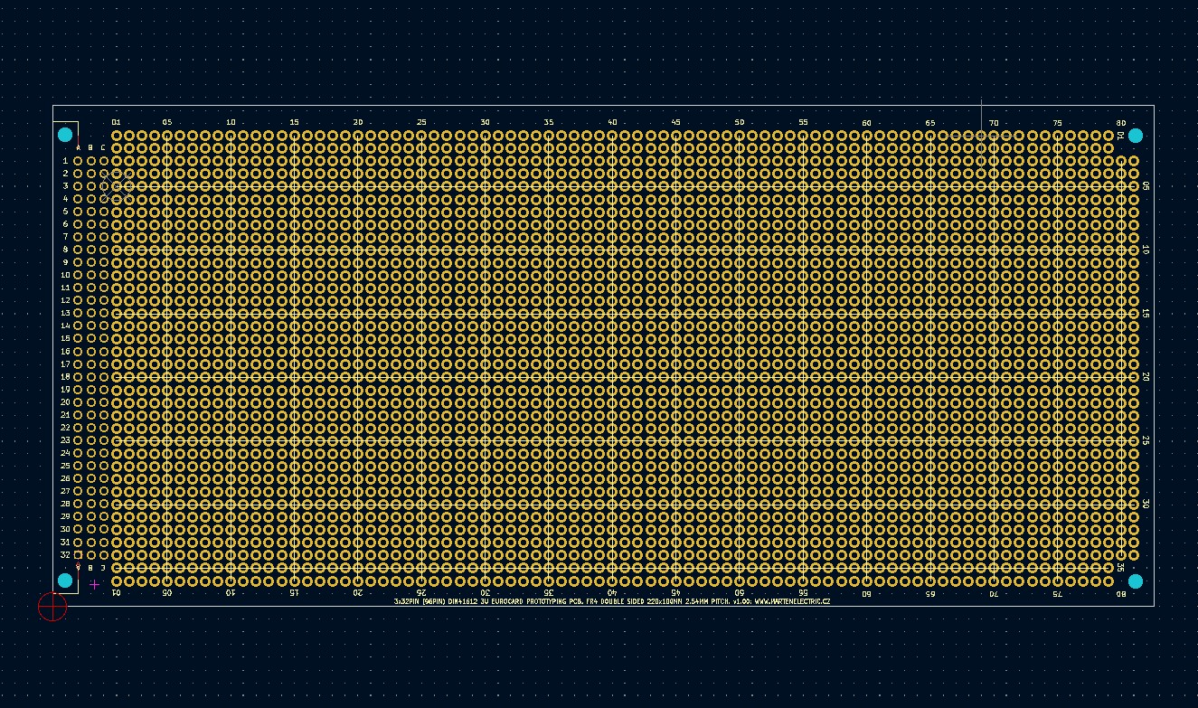
PCB design layout
Specifications
Board Type: Prototype Board
Board Material: FR4-Standard Tg 130-140C Epoxy Glass Composite
Layers: Double sided
PCB Colour: Green colour solder mask, white silk screen lettering
Surface Finish: Lead free HASL-RoHS
External size: 220x100mm
Board Thickness: standard 1.6mm fits in standard guide rail and standard Eurocard front panel
Pitch: 2.54mm (100.00 mils)
Hole matrix: 82 x 36 holes, Prototyping 2944 holes + 96 holes for DIN connector (3040 holes in total)
Hole size: 1.00mm
Mounting holes: Standard pitch DIN 41612. 4x mounting holes 2.50mm / 3.00mm
Board Connector / Footprint: DIN 41612 2x32pin or 3x32pin 64 / 96 Pin connector
Copper Thickness: 35um
Card weight: 66g
Bill of materials
| Identifier | Value | Qty | Notes |
|---|---|---|---|
| Printed Circuit Board | 220 x 100 mm DIN41612 3U prototyping card | 1 | v1.0 |
| Hardware | M2.5 x 10mm screw | 2 | |
| Hardware | M2.5 nut | 2 | |
| Connector | Female DIN 41612 96pin 3x32pin right angle connector | 1 | |
| Connector | Female DIN 41612 64pin 2x32pin right angle connector | 1 | 2nd alternative use |
| Connector | 2x32pin 64pin PCB edge right angle connector 0.1" pitch | 1 | 3rd alternative use |
Assembly instructions and notes
■ Gerber files contain " JLCJLCJLCJLC" to silk layer. You can specify a location of the order number, select the "Specify a location" option when you place an order. Only if you order via JLCPCB
■ Fit Female and Male DIN 41612 96pin 3x32pin right angle connector or alternatives you wish to use
■ Use M2.5 screws and nuts to hold DIN connectors in place, thse don't need to be fitted to achieve strong mechanical connection however
■ Use a temperature-controlled soldering station and quality solder. Take care not to leave solder bridges as any short circuit will most likely lead to failures
Schematic
| File type | File name | File size | Last modified |
|---|---|---|---|
| Not available for this project. | - | - | - |
Design Files
| File type | File name | File size | Last modified |
|---|---|---|---|
| PCB layers v1.0 | 259 kB | 16/05/2022 | |
| Gerbers 220x100mm, 2 Layer FR4. v1.0 | 113 kB | 16/05/2022 | |
| Solder paste stencil | Not available for this project | - | - |
Photographs
Not available for this project.
Versions and revisions
This section lists the project version and revision history.
v1.0
■ No revisions available for this project