Marten Electric 電気テン @ Home
Vintage audio gear connoisseur, computer enthusiast, time nut, music lover, vintage games gamer, nerd, tinkerer and shady electronic projects makerIBM PC AT 16-bit ISA Bus Riser Extender Card
Introduction
The ISA 16-bit extender riser card is a specialized type of test card that is typically used in industrial and commercial settings for production testing, prototyping, diagnostic and troubleshooting of ISA or footprint compatible cards.
Extender card is inserted into the ISA slot on the backplane or motherboard, and then the ISA card under test is inserted into the PCB edge connector socket on the riser card. This setup enables users to test the card in situ for issues without the need to remove it from the motherboard. This is particularly useful in situations where the tested cards are challenging to access and/or devices require disassembly, which can help users to diagnose issues that may only occur when the PCBs are connected to the system.
I have originally designed this backplane for few of my projects, but this turn out so well that I have now posted all schematic, gerber files and documentation to fellow enthusiast such as yourself. Perhaps (and I hope) content in this obscured corner of interwebs will inspire you to start your own projects.
Design overview
You will usually fit this card in industry standard 16-bit ISA PCB edge card connector. Riser extender card his will also fit into 8-bit connector, however you have to make sure there is no physical obstruction on backplane or motherboard. For 8-bit applications please refer to IBM PC XT 8-bit ISA Bus Riser Extender Card. PCB was designed according to standard mechanical dimensions, therefore connectors' mechanical positions will match perfectly with PCB edge connector and rear PC brackets should you decide to use this solution.
Main design features:
Tested and proven design with many revisions. Raiser Extender PCB has been designed to be very flexible and can be used with large variety of industry standard power and signal connections:
■ Signal traces - (passive termination) are not terminated nor have determined pinouts; allowing you to configure the backplane to exactly match the requirements of the system. Traces are wide apart thus minimizing crosstalk.
■ Test points - The riser card features 3x32pin AB + 2x18pin CD rows for test points and sports test point loops or 0.1" Dupont header connectors footprint that facilitate easy injection of test signals and/or monitoring of bus signals with test equipment (oscilloscope, logic analyser, multimeter etc.) during the manufacturing and testing of the PCB.
■ Power connectors - Power tracks size increased for higher power rating and noise suppression.
Separation of all power and ground traces to ease trouble shooting.
Bracket mounting holes are not electrically connected.
■ Mechanical - PCB format is large enough to be robust and extend card under test above majority of PC cases due to leght of 169mm (including connector).
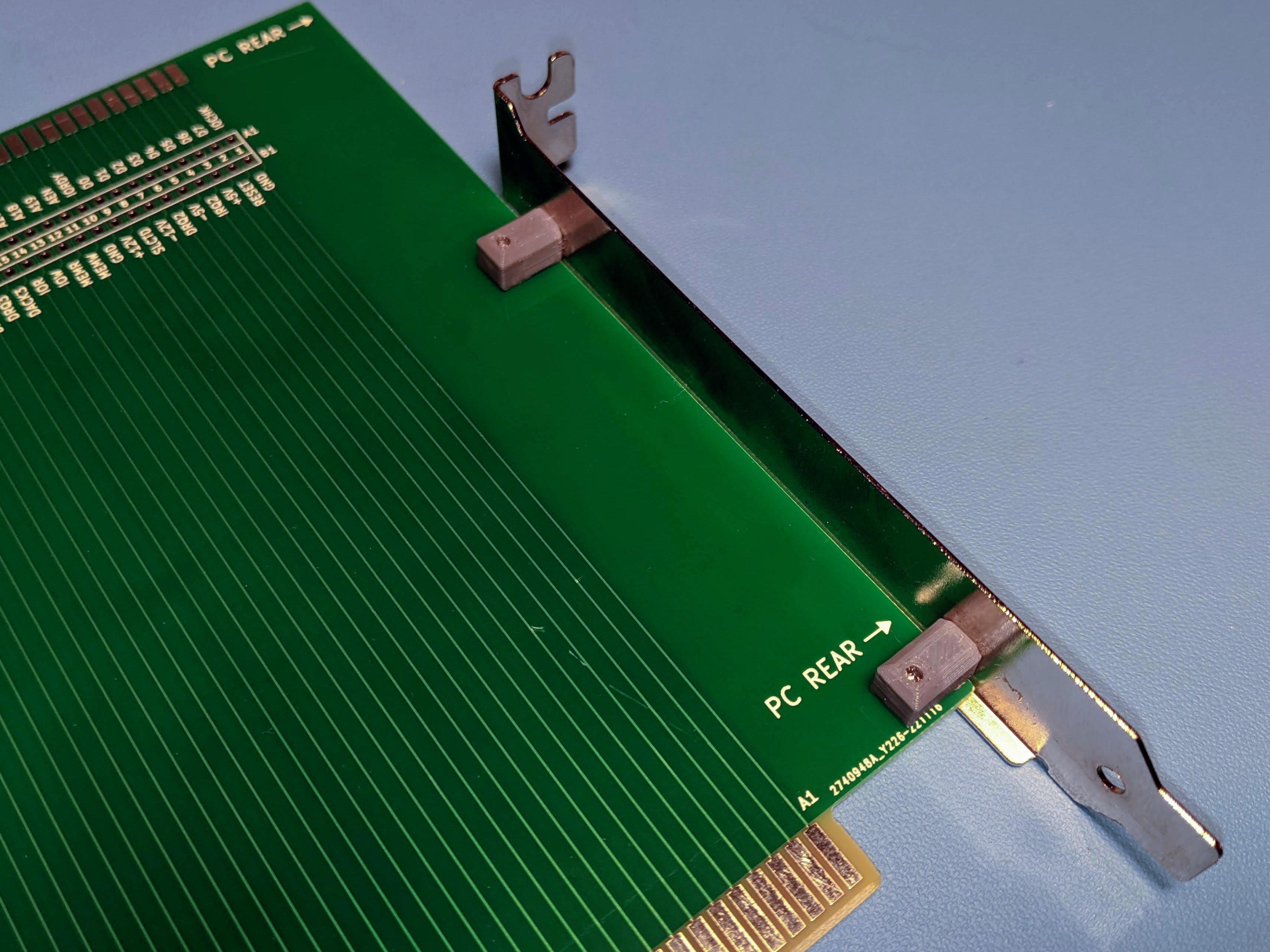
PCB footprint (from v1.0) accomodates holes for installation of rear PC case bracket. PCB sports standard 2x49pin PCB edge connectors with 45° chamfered edge for easy insertion and comes with industry standard 98pin (2x31 + 2x18 pin) ISA Bus edge connector.
These boards look absolutely gorgeous in standard green solder mask if you going for that standard industrial look. I can advise you where to buy PCB Edge connector and rear support bracket. Rear bracket is supported by 3D printed parts. STL file for download below.
ʕっ•ᴥ•ʔっ
Except where otherwise noted, content on this site is licensed under a Creative Commons Attribution 4.0 International license. CC-BY-4.0
I have created content on this website free to use for personal, educational and commercial purposes. If you like or use my work, please mention me or perhaps consider a donation.
| or |
... but if you feel like getting something for nothing isn't your cup of tea (completely understandable) (ಥ﹏ಥ) and a prefer to support me and get something back in return, then you can purchase directly on my eBay or Tindie shop. However if you are still up for an adventure */in very positive way/* (and are happy to have PCB's made yourself in your favourite PCB house - PCBWay is highly recommended), then carry on, download gerber files and have fun! ( ͡° ͜ʖ ͡°)


EDA preview
click on pictures to enlarge


PCB design layout


Specs
Board Type: Prototype Board
Board Material: FR4-Standard Tg 130-140C Epoxy Glass Composite
Layers: Double sided
PCB Colour: Green colour solder mask, no screen lettering
Surface Finish: Lead free HASL-RoHS
External size: 162 x 155mm bare PCB; 162 x 169mm including connector
Board Thickness: standard 1.6mm - fits in standard 16-bit ISA card PCB edge connector
Board Connector / Footprint: 98pin 2x31pin + 2x18pin ISA Bus connector with 45° chamfered edge, 98pin (2x49pin) PCB edge card connector socket
Copper Thickness: 35um
Card weight: 130g including connector and rear bracket
Bill of materials
| Identifier | Value | Qty | Notes |
|---|---|---|---|
| Printed Circuit Board | 16-bit ISA riser PCB 162 x 155mm 2 Layer FR4 | 1 | v1.2 |
| Connector | 2x49pin 98pin PCB edge right angle connector 0.1" pitch | 1 | |
| Mechanical support | Rear PC case slot metal bracket | 1 | |
| Mechanical support | 3D printed mount bracket | 2 | v1.0 |
| Mechanical support | Wood Screw M2.6 x 6 x 6 mm | 4 |
Assembly instructions and notes
■ for 45° chamfered edge use option Gold Fingers and 45°finger chamfered option when sending PCB to matufacture.
■ To fit nicely 2x49pin PCB edge card connector you need to bend legs inwards by pusing againts hard flat surface, repeat for both sides untill you have nice evenly bend legs
■ To solder PCB edge connector you need to pack up end of card so that PCB edge connector isn't pissed tilted. Solder one pin from each end first and carry on further if connector is staright.
■ Use a temperature-controlled soldering station and quality solder. Take care not to leave solder bridges as any short circuit will most likely lead to catastrophic failures and explosions :)
■ 3D print plastic brackets
■ Pre drill rear pc case metal bracket should you wish to use it
■ Fit pastic and metal bracket with recommende woodscrews, leave screw loose. Fit card in the desired slot, adjust position and tighten screws.
■ Enjoy the labour of love!
■ Jokes apart; when using a riser extender test card, it is important to exercise caution when working with sensitive electronic components. Users should ensure that the device is turned off before inserting or removing any cards under test. This precautionary measure can help prevent damage to the components and the system.
Schematic
| File type | File name | File size | Last modified |
|---|---|---|---|
| ISA 8-bit extender Schematic v1.0 | 83 kB | 20/06/2021 | |
| ISA 8-bit extender Schematic v1.0 | 154 kB | 20/06/2021 |
Design Files
| File type | File name | File size | Last modified |
|---|---|---|---|
| PCB layers; v1.2 | 167 kB | 14/05/2023 | |
| Gerbers 142 x 97 mm, 2 Layer FR4; v1.2 | 187 kB | 14/05/2023 | |
| 3D printed bracket for rear case metal support; v1.0 | 9 kB | 29/11/2022 | |
| Solder paste stencil | Not available for this project | - | - |
Photographs
click on pictures to enlarge
gerber files and photographs may vary; v1.0 pictured


3D printed bracket for rear case metal support

Versions and revisions
This section lists the project version and revision history.
v1.2
■ All tracks edges rounded
■ Teardrops added to all THT and SMT pads and tracks
■ Various Silkscreen updates
■ Edge connector footprint update
v1.1
■ Mechanical holes size and position amened
■ Solder mask adjusted on PCB edge card connector side to make it easy to solder.
■ Silkscreen updates
v1.0
■ Prototype based on already existing 8-bit ISA riser card
Last page update: 14 May 2023